(1)、This product is a kind of voltage transformer in current mode. Though the series
resistance in the circuit, primary current converts voltage into current. After this
transformer completing current transformation, the secondary output current signal
goes though a sample resistance and then it converts into the needed voltage.
(2)、Wide measuring range
b. Electrical Parameters:
(1)、Rated input current: 1~5mA (According to customers’ requirements)
(2)、Rated output current: 1~5mA (According to customers’ requirements)
(3)、Non-linearity: Ratio error <±0.1%; Phase error <±5′
(4)、Range of linearity:10%~2000% (or more)rated current
(5)、Frequency characteristic: 45~800HZ
(6)、Insulation resistance: 500MΩ @500VdC
(7)、Power frequency withstands voltage: 3kV 2mA 1min
(8)、Output load resistance:≤400Ω
(9)、Operating temperature: -40℃~+85℃
(10)、Structure:Epoxy encapsulating
(11)、Outer casing:PBT heat-resistant material or ABS flame-retardant material
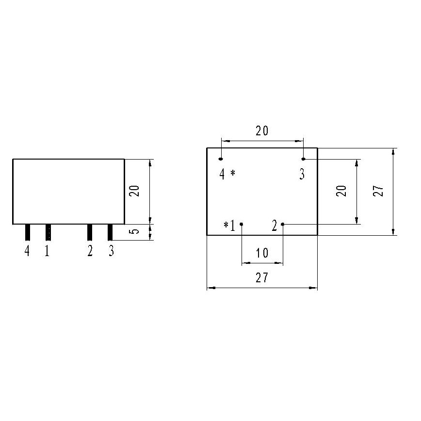
(12)、Terminal:input and output→pins
(13)、Main Specifications: Current ratio between primary side and secondary side
2mA:2mA 2.5mA:2.5mA 5mA:5mA 10mA:10mA
c. Type Implication: ZR H C XX
ZR -----Zhongrui Electrical Technical Co., Ltd
H -----Product’s variety code(H、Ultra-miniature transformer)
V -----Classification code (V、Voltage)
XX -----Product’s outer casing code

d. Method of Application: "" />
ZRH-VXX Series Current Transformer
Typical application circuit (as the figure shows)

Recommended circuit diagram of ZRH-V11
xml:namespace prefix = v ns = "urn:schemas-microsoft-com:vml" />
Turn ratio of the transformer is 1:1, rated current ratio is 2mA:2mA, or 2.5mA:2.5mA etc. When using, the resistance must be cascaded in the primary circuit, so that the voltage can be converted into current. Adjust the feedback resistance, though the function of operational amplifier, then you can get the needed voltage at the output terminal.
Practical example:
Design a circuit with ZRHXX-V, its rated input voltage is 100V and rated output voltage is 5V.
The circuit parameter is shown as follows: (In order to set the circuit parameter, you must set the figure for current limiting resistance and feedback resistance at first.)
First of all, set 2mA as the rated primary resistance, and the current limiting resistance can be calculated like this: R′=100V/2mA=50 KΩ. Then set 51 KΩ,1W for the resistance. Now the actual rated primary resistance can be calculated like this: I=100V/51.11 KΩ=1.96mA (set 0.11 KΩ for TRxml:namespace prefix = st1 ns = "urn:schemas-microsoft-com:office:smarttags" />
If you require the output voltage to be perfectly accurate, you can choose 2.4KΩ or 2.5KΩ as your resistance, in addition, you can cascade an adjustable resistance(200Ω)for fine tuning;Or choose 2.7 KΩ as your resistance, cascading an adjustable resistance (50KΩ) for fine tuning,so that you can get your required accuracy.
Generally, Capacitance’s empirical value will be 0.01-0.033µF. Resistance will be 200-300KΩ adjustable resistance. IC will be OP07 or µA741 or other universally operational amplifier.
Particular illustration:
Set the resistance in parallel at the secondary side of the transformer to get the required voltage. The resistance should not be too large, generally it is no more than 400Ω. If the resistance is too large, linearity of the transformer will be not so good that phase shift will increase.

